WELDING
Welding is a materials joining process which produces coalescence of materials by heating them to suitable temperatures with or without the application of pressure or by the application of pressure alone, and with or without the use of filler material.
Welding is used for making permanent joints. It is used in the manufacture of automobile bodies, aircraft frames, railway wagons, machine frames, structural works, tanks, furniture, boilers, general repair work and ship building.
TYPES
· Plastic Welding or Pressure Welding
The piece of metal to be joined are heated to a plastic state and forced together by external pressure
(Ex) Resistance welding
· Fusion Welding or Non-Pressure Welding
The material at the joint is heated to a molten state and allowed to solidify
(Ex) Gas welding, Arc welding
Classification of welding processes:
(i). Arc welding
1. Carbon arc
2. Metal arc
3. Metal inert gas
4. Tungsten inert gas
5. Plasma arc
6. Submerged arc
7. Electro-slag
(ii). Gas Welding
1. Oxy-acetylene
2. Air-acetylene
3. Oxy-hydrogen
(iii). Resistance Welding
1. Butt
2. Spot
3. Seam
4. Projection
5. Percussion
(iv) Thermit Welding
(v) Solid State Welding
1. Friction
2. Ultrasonic
3. Diffusion
4. Explosive
(vi) Newer Welding
1. Electron-beam
2. Laser
(vii) Related Process
1. Oxy-acetylene cutting
2. Arc cutting
3. Hard facing
4. Brazing
5. Soldering
Arc welding methods
1. Metal arc welding
It is a process of joining two metal pieces by melting the edges by an electric arc. The electric arc is produced between two conductors. The electrode is one conductor and the work piece is another conductor. The electrode and the work piece are brought nearer with small air gap. (3mm app.)
When current is passed an electric arc is produced between the electrode and the work piece. The work piece and the electrode are melted by the arc. Both molten piece of metal become one. Temperature of arc is about 4000°c Electrodes used in arc welding are coated with a flux. This flux produces a gaseous shield around the molten metal. It prevents the reaction of the molten metal with oxygen and nitrogen in the atmosphere. The flux removes the impurities from the molten metal and form a slag. This slag gets deposited over the weld metal. This protects the weld seam from rapid cooling. Fig.1 shows arc welding process.
Equipments:(Refer Fig 2)
· A welding generator (D.C.) or Transformer (A.C.)
· Two cables- one for work and one for electrode
· Electrode holder
· Electrode
· Protective shield
· Gloves
· Wire brush
· Chipping hammer
· Goggles
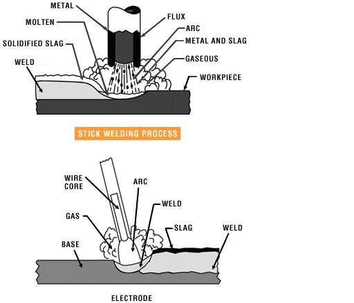 |
Fig. 1 Arc Welding
|
 |
Fig 2 Electric Arc Welding Equipments
|
Advantages:
Ø Most efficient way to join metals
Ø Lowest-cost joining method
Ø Affords lighter weight through better utilization of materials
Ø Joins all commercial metals
Ø Provides design flexibility
Limitations:
1. Manually applied, therefore high labor cost.
2. Need high energy causing danger
3. Not convenient for disassembly.
4. Defects are hard to detect at joints.
2. Carbon arc welding:
In carbon arc welding, the intense of heat of an electric arc between a carbon electrode and work piece metal is used for welding. DC power supply is used. The carbon electrode is connected to negative terminal and work piece is connected to positive terminal, because positive terminal is hotter (4000°c) than the negative terminal (3000°c) when an arc is produced. So carbon from the electrode will not fuse and mix up with the metal weld. If carbon mixes with the weld, the weld will become weak and brittle. To protect the molten metal from the atmosphere the welding is done with a long arc. In this case, a carbon monoxide gas is produced, which surrounds the molten metal and protects it.
Carbon arc welding is used to weld both ferrous and non ferrous metals. Sheets of steel, copper alloys, brass and aluminium can be welded in this method.( Refer Fig 3)
 |
|
Fig 3 Carbon Arc Welding
|
Comparison of A.C. and D.C. arc welding
Alternating Current (from Transformer)
|
Direct Current (from Generator)
| |
1
|
More efficiency
|
Less efficiency
|
2
|
Power consumption less
|
Power consumption more
|
3
|
Cost of equipment is less
|
Cost of equipment is more
|
4
|
Higher voltage – hence not safe
|
Low voltage – safer operation
|
5
|
Not suitable for welding non ferrous metals
|
suitable for both ferrous non ferrous metals
|
6
|
Not preferred for welding thin sections
|
preferred for welding thin sections
|
7
|
Any terminal can be connected to the work or electrode
|
Positive terminal connected to the work
Negative terminal connected to the electrode
|
GAS WELDING
Oxy-Acetylene welding
In gas welding, a gas flame is used to melt the edges of metals to be joined. The flame is produced at the tip of welding torch. Oxygen and Acetylene are the gases used to produce the welding flame. The flame will only melt the metal. A flux is used during welting to prevent oxidations and to remove impurities. Metals 2mm to 50mm thick are welded by gas welding. The temperature of oxyacetylene flame is about 3200°c. Fig 3 shows Gas welding equipments.
Gas Welding Equipment
1. Gas Cylinders
Pressure
Oxygen – 125 kg/cm2
Acetylene – 16 kg/cm2
2. Regulators
Working pressure of oxygen 1 kg/cm2
Working pressure of acetylene 0.15 kg/cm2
Working pressure varies depends upon the thickness of the work pieces welded.
3. Pressure Gauges
4. Hoses
5. Welding torch
6. Check valve
7. Non return valve
 |
| Fig- 4 Gas Welding Equipment |
TYPES OF FLAMES
• When acetylene is burned in air, it produces a yellow sooty flame, which is not enough for welding applications
• Oxygen is turned on, flame immediately changes into a long white inner area (Feather) surrounded by a transparent blue envelope is called Carburizing flame (30000c)
• This flames are used for hardening the surfaces
• Addition of little more oxygen give a bright whitish cone surrounded by the transparent blue envelope is called Neutral flame (It has a balance of fuel gas and oxygen)
• Most commonly used flame because it has temperature about 32000c
• Used for welding steels, aluminium, copper and cast iron
• If more oxygen is added, the cone becomes darker and more pointed, while the envelope becomes shorter and more fierce is called Oxidizing flame
• Has the highest temperature about 34000c
• Used for welding brass and brazing operation
Fig 4 shows the types of flames.
Fig 5 Types of Gas Flames
Advantages
1. Equipment has versatile
2. Same equipment can be used for oxy acetylene cutting and brazing by varying the torch size
3. Heat can controlled easily
Disadvantages
1. Slower process
2. Risk is involved in handling gas cylinders
GAS CUTTING
• Ferrous metal is heated in to red hot condition and a jet of pure oxygen is projected onto the surface, which rapidly oxidizes
• Oxides having lower melting point than the metal, melt and are blown away by the force of the jet, to make a cut
• Fast and efficient method of cutting steel to a high degree of accuracy
• Torch is different from welding
• Cutting torch has preheat orifice and one central orifice for oxygen jet
• PIERCING and GOUGING are two important operations
• Piercing, used to cut a hole at the centre of the plate or away from the edge of the plate
• Gouging, to cut a groove into the steel surface
 |
| Fig 6 Automatic Gas Cutting |
 |
| Fig 7 Manual Gas Cutting |
Weld joint:
There are 5 basic joint types in welding
• Butt joint: Two materials are in the same plane, joined from the edges.
• Corner joint:The corners of two materials form a right angle and joined.
• Lap joint: Two parts overlaps.
• Tee joint: One part is perpendicular to the other, making a T shape.
• Edge joint: Edges of the two materials joined.
Types of weld
1. Fillet weld: Used in T joints,corner joints, lap joints.
2. Groove weld:Used in butt joints.
3. Plug weld: Used in lap joints.
4. Slot weld: Used in lap joints.
5. Spot weld: Used in lap joints.
6. Seam weld: Used in lap joints.
7. Flange weld:Used in edge joints.
8. Surfacing weld:Not a joining process, it is used to increase the thickness of the plate, or provide a protective coating on the surface.
 |
| Fig 8 Types of Weld Joints |
Weldability is the ease of a material or a combination of materials to be welded under fabrication conditions into a specific, suitably designed structure, and to perform satisfactorily in the intended service
Brazing and Soldering
Brazing
It is a low temperature joining process. It is performed at temperatures above 840º F and it generally affords strengths comparable to those of the metal which it joins. It is low temperature in that it is done below the melting point of the base metal. It is achieved by diffusion without fusion (melting) of the base
Depending upon the method of heating, brazing can be classified as
1. Torch brazing
2. Dip brazing
3. Furnace brazing
4. Induction brazing
 |
| Fig 9 Brazing |
Advantages:
Ø Dissimilar metals which canot be welded can be joined by brazing
Ø Very thin metals can be joined
Ø Metals with different thickness can be joined easily
Ø In brazing thermal stresses are not produced in the work piece. Hence there is no distortion
Ø Using this process, carbides tips are brazed on the steel tool holders
Disadvantages:
Ø Brazed joints have lesser strength compared to welding
Ø Joint preparation cost is more
Ø Can be used for thin sheet metal sections
Soldering
It is a low temperature joining process. It is performed at temperatures below 840ºF for joining.
Soldering is used for,
• Sealing, as in automotive radiators or tin cans
• Electrical Connections
• Joining thermally sensitive components
• Joining dissimilar metals
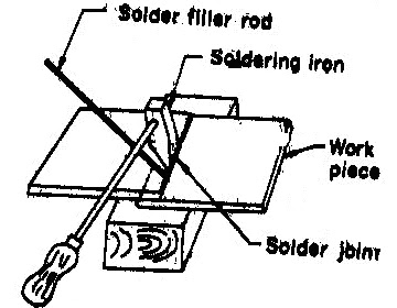 |
| Fig 9 Soldering |


